Traffic Detection
The Radar AI LPR Network Camera not only supports the embedded LPR algorithm, but also the deep learning algorithm based on the AI platform, which can achieve higher detection accuracy and richer intelligent functions.
The Radar AI LPR camera is a truly all-in-one integrated camera. The radar module is directly integrated in the camera, making installation more convenient.
In this page, you can configure the Traffic Detection of Radar model.
- Make sure your camera model is Milesight Radar AI LPR Cameras.
- For more details, please refer to https://milesight.freshdesk.com/a/solutions/articles/69000797257.
Step1: Enable the traffic detection.
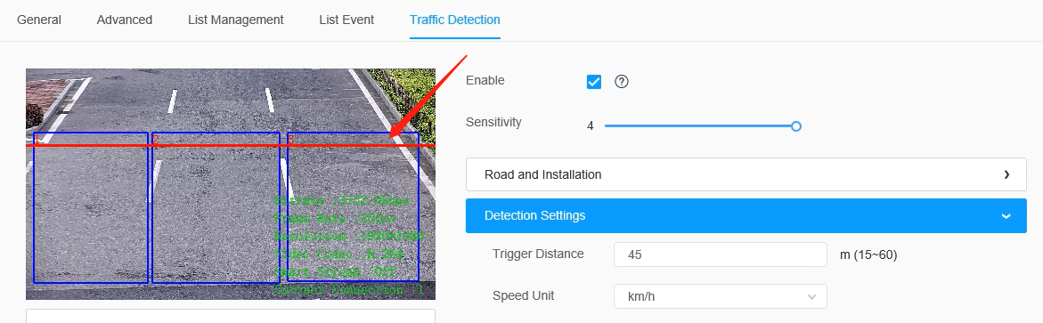
Go to the “LPR”--> “Settings”--> “Traffic Detection”, check the checkbox to enable Traffic Detection.
Then adjust the detection sensitivity of the radar module, levels 1~4 are available. The higher the sensitivity, the easier the target is to be detected. Users can adjust the detection sensitivity as needed to avoid some missing or false detection, such as false detection caused by rain hitting the radar board.
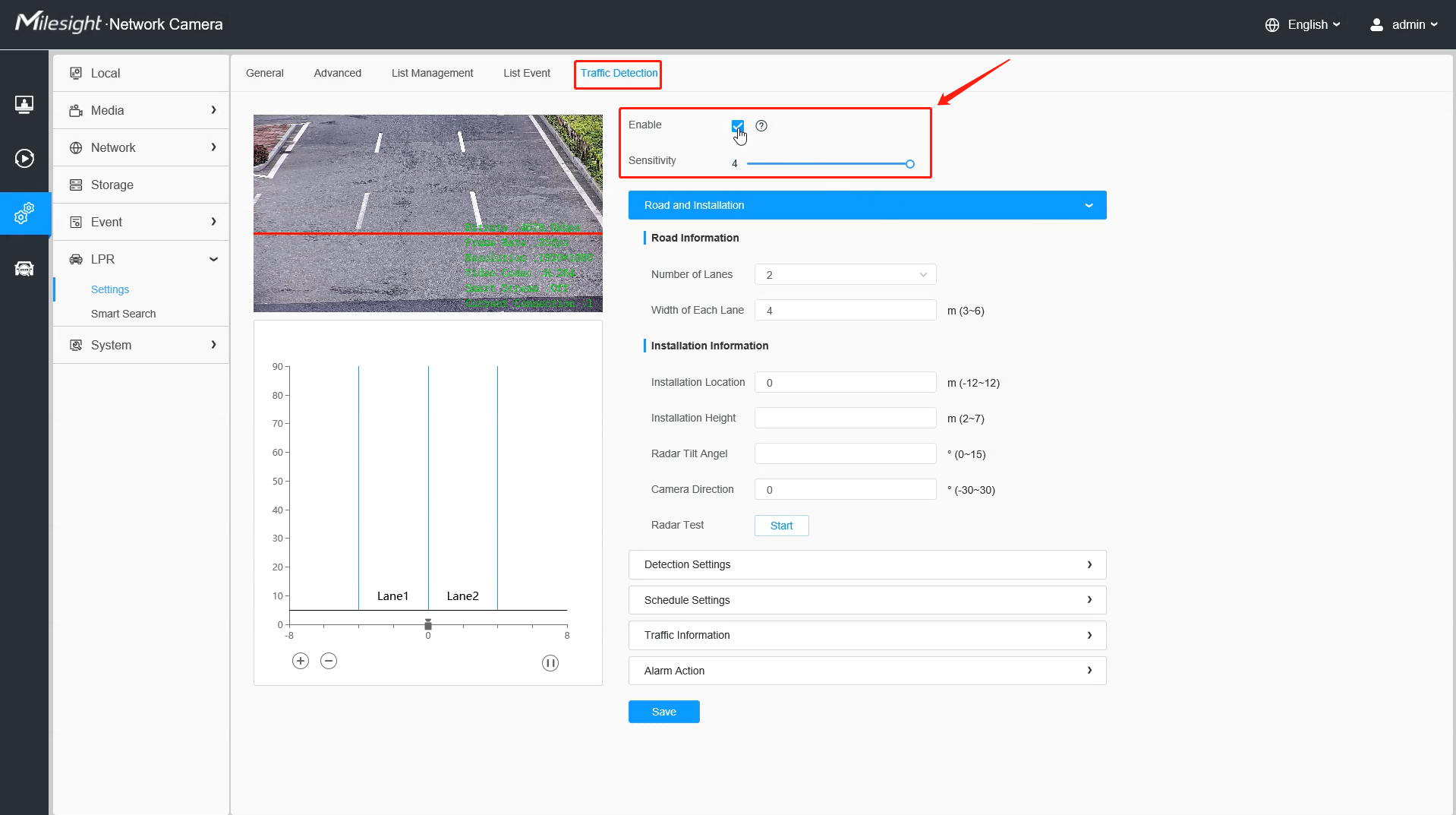
Step2: Fill in the road and installation information as shown below.
| Parameters | Function Introduction |
|---|---|
|
Number of Lanes & Width of Each Lane |
Please fill in the number of lanes and the width of each lane according to the actual scene. It supports up to 4 lanes, and the width range of each lane is from 3 to 6 meters. |
|
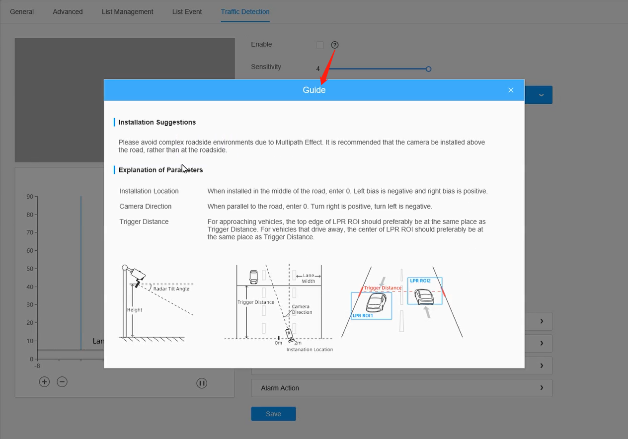
Installation Location |
Please fill in the installation position of the camera on the road, the range is -12 to 12 meters, and the default is 0. If the camera is installed in the middle of the road, fill in 0, otherwise, fill in the corresponding offset distance. It should be noted that the installation position needs to be confirmed as a positive or negative number. With the center of the road as the zero point, if the camera is installed on the left side of the road, it is defined as a negative number, and if it is on the right side, it is defined as a positive number. |
|
Installation Height |
Please fill in the installation height according to the actual installation height of the camera, the range is 2 to 7 meters. |
|
Radar Tilt Angle |
Please fill in the Radar Tilt Angle according to the actual installation angle between the camera's field of view and the horizontal. |
|
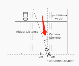
Camera Direction |
Please fill in the angle between the direction of the camera installation and the road, the angel range is -30°~30°, and the default is 0°. When the camera is parallel to the road, enter 0. Turn right is positive, turn left is negative as shown below.
|
|
Radar Test |
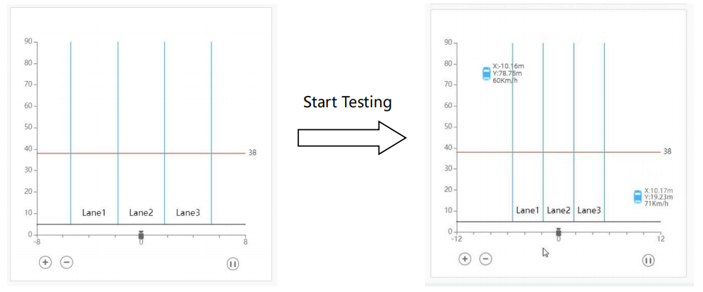
After completing the above configuration, you can click the test button, then the above configuration will be automatically saved and the radar module will start to test with the maximum sensitivity and maximum detection range, which is not limited by the lane configuration. In this way, the user can flexibly adjust the configuration according to the position of the target in the coordinates to achieve the most matching configuration.
Note: After 30 seconds of testing, the radar test function will be
automatically turned off to prevent customers from forgetting to
turn off the function.
|
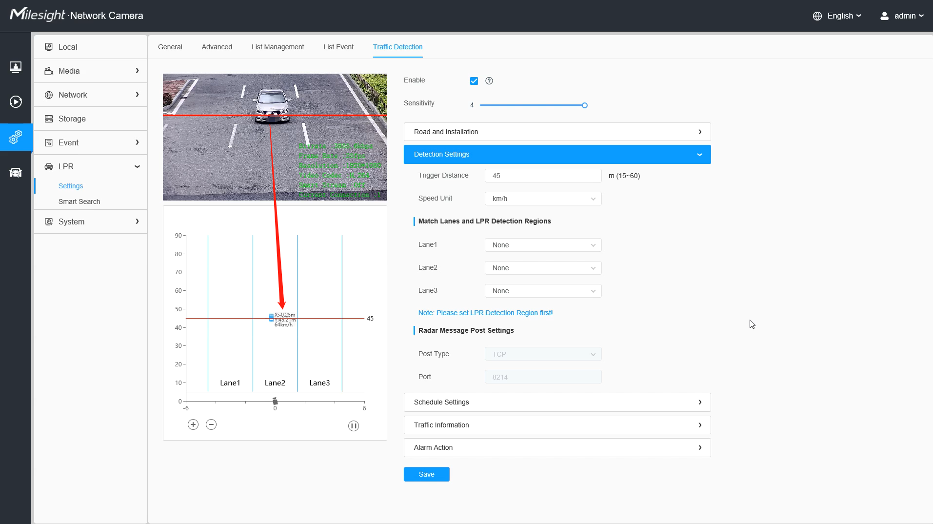
Step3: Set Detection Settings.
| Parameters | Function Introduction |
|---|---|
|
Trigger Distance |
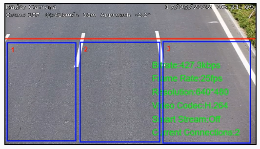
As shown in the radar configuration page in the figure below, there will be a red line in the preview box of the configuration page. The red line is the position that can be adjusted up and down, and the Trigger Distance is the horizontal distance from the red line to the radar. When the license plate is detected in the LPR detection area, the recognized LPR detection result will match the radar data of the vehicle passing the trigger distance at the same time. Therefore, please ensure that the position of the red line in the video is the actual horizontal distance from the red line to the radar in the scene, to facilitate better matching between the LPR data and Radar data.
For the Oncoming Vehicles:
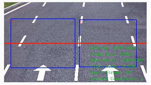
For the Leaving Vehicles:
Note: To ensure
relative accuracy, users need to fill in the trigger distance
after actual measurement, we recommend three ways to get the
trigger distance. For more details, please refer to https://milesight.freshdesk.com/a/solutions/articles/69000797257. |
|
Speed Unit |
Select the speed unit as km/h or mph to meet the needs of customers in different regions. |
|
Match Lanes and LPR Detection Regions |
Please match the LPR detection region and lane one by one according to the actual scene. |
|
Radar Message Post Settings |
It supports the compatibility of radar data with back-end software via TCP, such as Milesight VMS Enterprise. |
After completing the Road&Installation Settings and Detection Settings, these information will be dynamically matched with the coordinate map in the lower left corner, and the detected target will also be dynamically displayed on the coordinate map, which is convenient for users to view the detection results in real time.
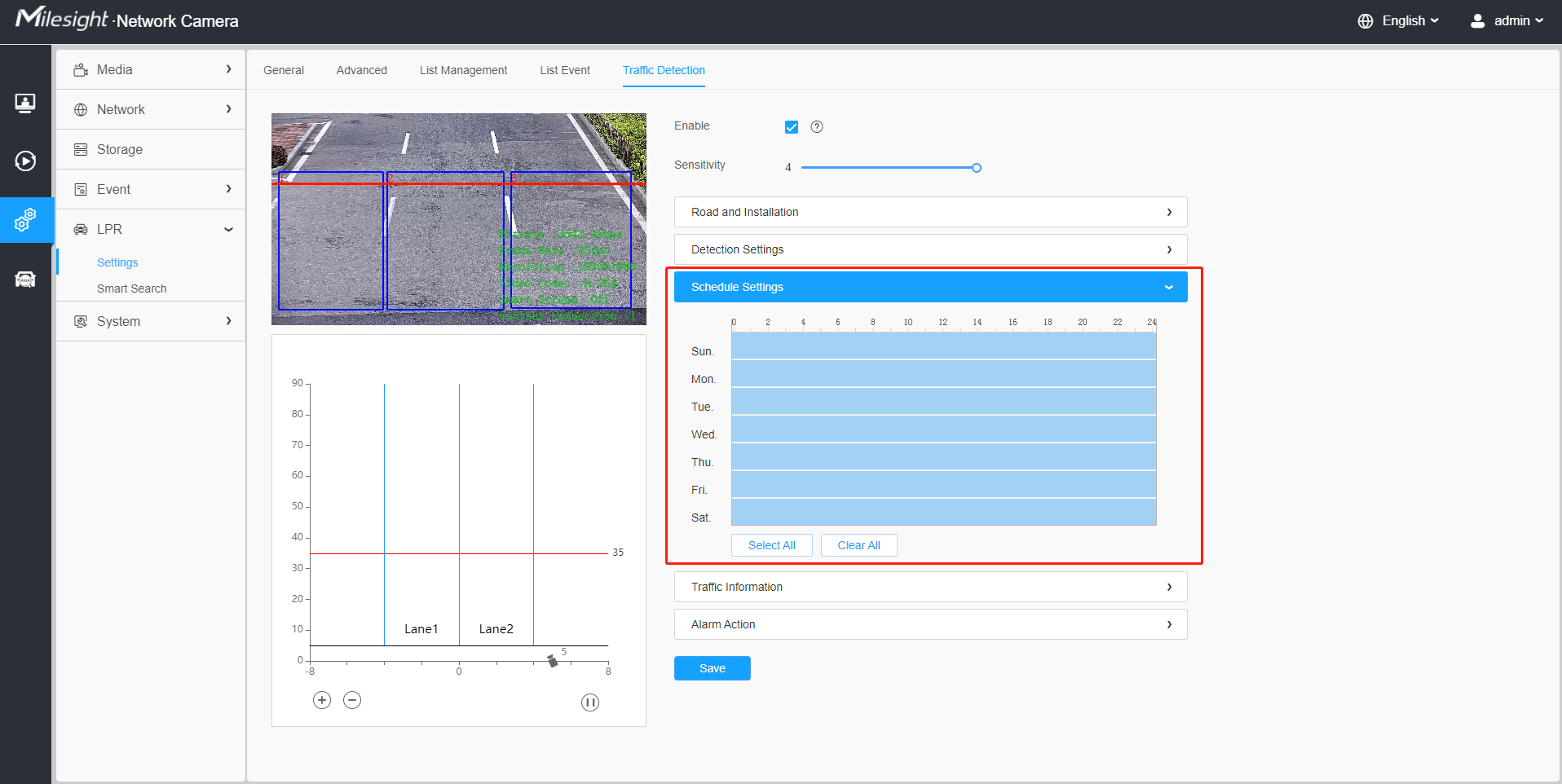
Step4: Schedule Settings.
Set the effective time of traffic detection.
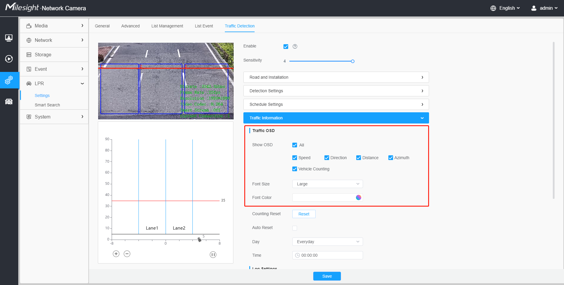
Step5: Traffic OSD Settings.
Customers can choose the information that needs to be displayed in Live Video and the display format, such as color, size, etc.
| Parameters | Function Introduction |
|---|---|
| Show OSD |
Users can choose the information they want to display in Live Video, including Speed, Direction, Distance, Azimuth and Vehicle Counting. |
| Font Size&Font Color |
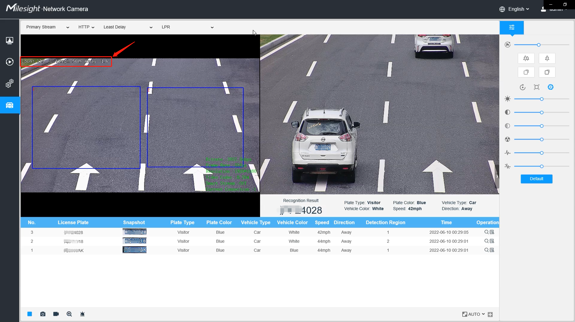
The font size and color of the OSD display, the default size is Medium; When Speed, Direction, and Vehicle Counting are checked, the Live View interface is displayed as shown in the figure below:
|
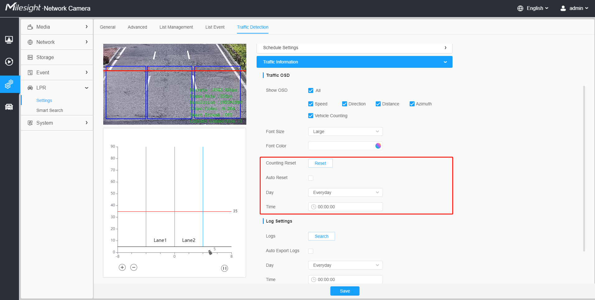
| Counting Reset | Click the "Reset" button to manually reset the vehicle count. |
| Auto Reset |
It is used to automatically clear the vehicle count at regular intervals (Just reset the OSD count for Live Video). After it is enabled, the interface is as shown in the figure below, just follow the prompts to set it.
|
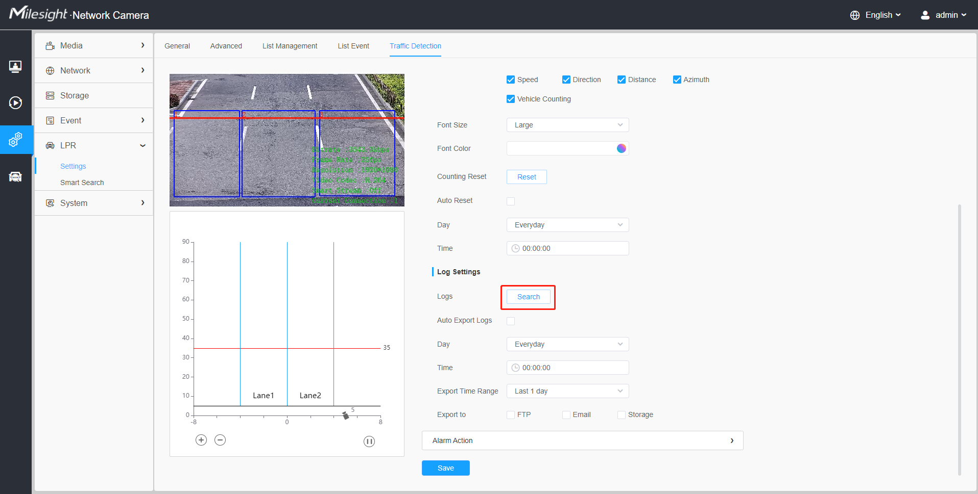
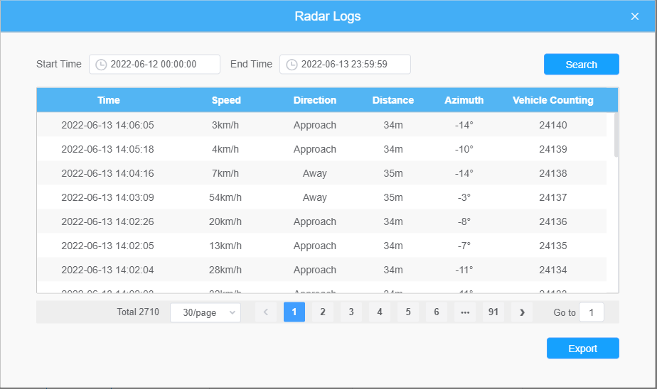
Step6: Log Settings.
Click the "Edit" button, and a pop-up window as shown in the figure below will appear, allowing users to search for various types of logs and supporting the log export function.
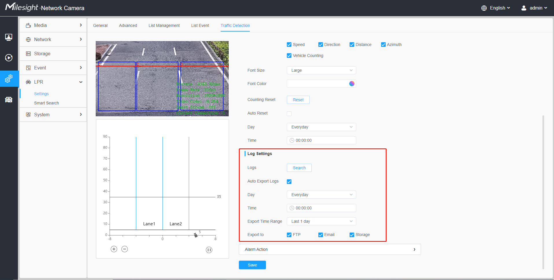
[Enable Auto Export Logs]: Support regular automatic export of logs to FTP, Email and Storage.
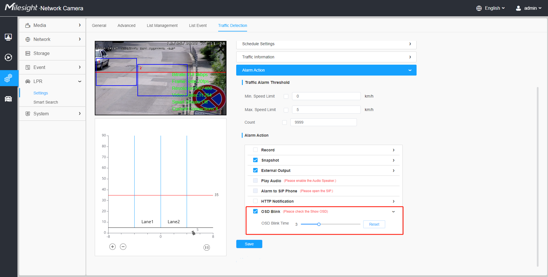
Step7: Traffic Alarm Threshold.
Used to set traffic alarm thresholds, such as maximum and minimum speed limits, and vehicle counting limits.
- OSD Blink
You need to enable the corresponding OSD first as shown in Figure 19. And then when an alarm is triggered, the OSD information will flash and alarm, and you can also set the duration of the OSD Blink Time, which supports 1~10s.
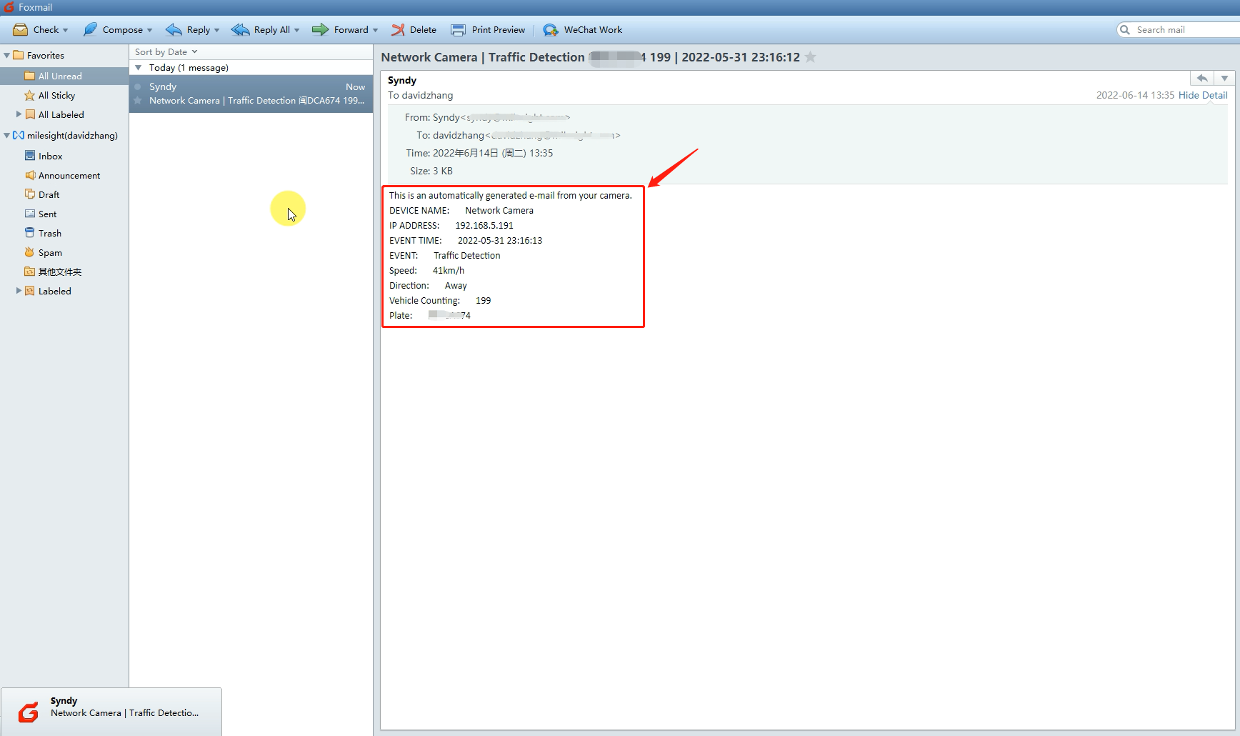
- Send Email
You need to configure the correct email information first. And then when an alarm is triggered, it will send the detection result to the corresponding email as shown below, including the license plate number, event type, vehicle speed, etc.