SG50 Custom Profile Template
This topic describes how to create a custom Profile template for SG50.
Background information
A Profile template contains both Basic Settings and Advanced Settings. Basic settings can edited with the visual interface provided by Milesight Development Platform, while the advanced settings can ONLY be edited in JSON format.
Follow the workflow below to create and apply a custom Profile template:
- Create a custom Profile template on Milesight Development Platform.
- Configure the basic settings with the visual interface.
- Configure the advanced settings in the JSON format.
- Save and apply the custom Profile template accordingly.
Step 1. Create a custom Profile template
- Log in to Milesight Development Platform.
- On the top bar, click Device then select the
Custom Profile Template tab.
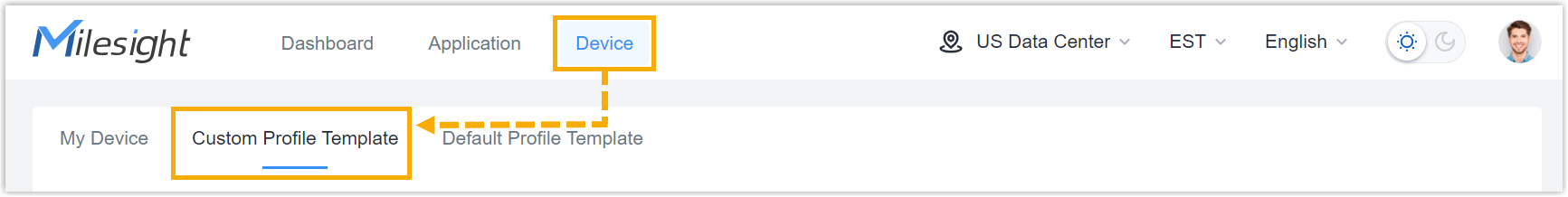
- Click Add.
- In the Basic Configuration section, configure the
basic information:
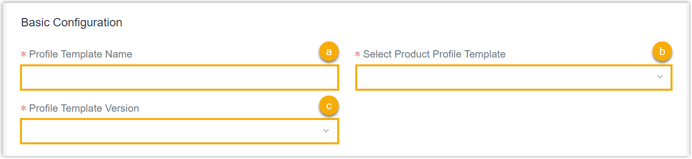
- In the Profile Template Name field, specify a name to help you identify this template.
- In the Select Product Profile Template field, search and select SG50_Profile_Template.
- In the Profile Template Version drop-down list, select the version of the Profile template.
Step 2. Configure the connecting platform
- Select the Generic Configuration tab.
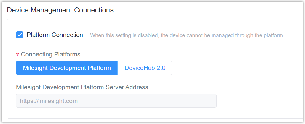
- In the Device Management Connections section, decide
whether to connect the device to Milesight platform for remote management
and configuration.
- Connect the device to Milesight Development Platform
- Retain the default settings.
- Connect the device to Milesight DeviceHub
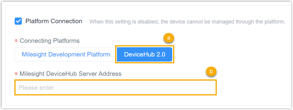
- In the Connecting Platforms field, select DeviceHub 2.0.
- In the Milesight DeviceHub Server Address field, enter the server address of the Milesight DeviceHub.
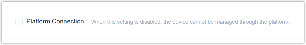
- Do NOT connect to Milesight platform
- Uncheck the Platform Connection.
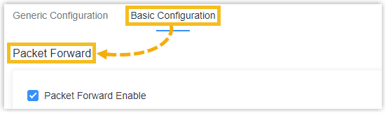
Step 3. Configure the Packet Forward settings
The gateway can serve as a packet forwarder to facilitate communication between LoRaWAN® end devices and the network server.
- Select
the Basic Configuration tab, then go to the
Packet Forward section.
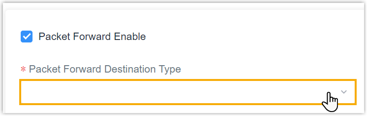
- In
the Packet Forward Destination Type drop-down list,
specify the packet forward type and configure the settings
accordingly
Type Settings Semtech Connect network server through the Semtech UDP protocol,which supports connecting to most mainstream network servers. - Server Address: Specify the LoRaWAN® server address.
- Port UP: The UDP port to forward uplinks from end device to network server.
- Port Down: The UDP port to forward downlinks from network server to end device.
Basics Station Connect network server through TCP protocol.Note: You only need to set up the LNS URI or CUPS URI. In this case, we take LNS URI as an example.- LNS URI: The URI of LoRaWAN®
network server. Enter the URI as below format and
replace <server-address> and
<port> as YOUR server address and
server
port:
wss://<server-address>:<port> or ws://<server-address>:<port>
- CA File(*.trust): Upload the CA certificate to secure the server domain.
- Client Certificate File(*.crt): Upload the client certificate file to verify the identity of the gateway.
- Client Key File(*.key): Upload the private key file to verify the identity of the gateway.
- GPS: Decide whether to forward gateway GPS data to network server.
Chirpstack-Generic Connect to Chirpstack via generic MQTT gateway bridge. - MQTT Address: Specify the LoRaWAN® network server IP address or domain.
- MQTT Port: Specify the LoRaWAN® network server port.
- User Credentials: After enabled, username and password are required to type for verification.
- TLS Authorization Enable: Decide whether
to enable TLS authorization. When enabled, you
need to specify the type of TLS certificates.
- CA signed server certificate: verify with the certificate issued by Certificate Authority (CA) that pre-loaded on the device.
- Self signed certificates: upload the custom CA certificates, client certificates and secret key for verification.
Remote Embedded NS Connect embedded network server of Milesight UG65/UG67/UG56 gateways.
Server Address: Specify the IP address or domain name of Milesight controller gateway.
MQTT Port: Specify the communication port to Milesight controller gateway.
Milesight Development Platform LNS Connect Milesight Development Platform LNS. This needs to select and enable Milesight Development Platform option on Service page and add the gateway to your platform account.
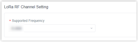
Step 4. Configure the LoRa RF Channel Setting
In the LoRa RF Channel Setting section, select the frequency of the device. The LoRaWAN® frequency plan used for the uplink and downlink frequencies and datarates. Available options depend on the gateway's model:-470M: CN470
-868M: EU868, RU864, IN865
-915M: US915, AU915, KR920, AS923-1&2&3&4
Step 5. Configure the LoRa Beacon
In the LoRa Beacon section, select the beacon period of the device. The Beacon Period is the interval of gateway sending beacons for Class B device time synchronization. 0 means the gateway will not send beacons. Please select the value as 128 if end device type is Class B.
![]()
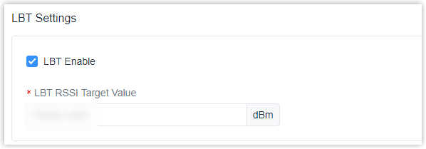
Step 6. LBT Settings
In the LBT Settings section, click to enable LBT and specify LBT RSSI Target Value. Listen before talk (LBT) is used to detect whether the downlink channel is idle and avoid channel access conflicts.
Step 7. Configure the Packet Forward Filters
In the Packet Forward Filters section, filter uplink packets via different conditions to reduce network congestion, save network traffic and ensure the safety operations.
- Select the filter mode as black list or white list.
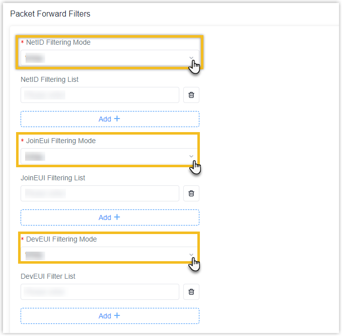
Setting Description NetID Filtering Mode Forward/Not forward the uplink packets that meet the NetID. - White List: Only forward the packets in this list to the network server.
- Black List: Only forward the packets except this list to the network server
JoinEui Filtering Mode Forward/Not forward the join request packets that meet the JoinEUI range. - White List: Only forward the packets in this list to the network server.
- Black List: Only forward the packets except this list to the network server
DevEUI Filtering Mode Forward/Not forward the join request packets that meet the DevEUI range.
- White List: Only forward the packets in this list to the network server.
- Black List: Only forward the packets except this list to the network server
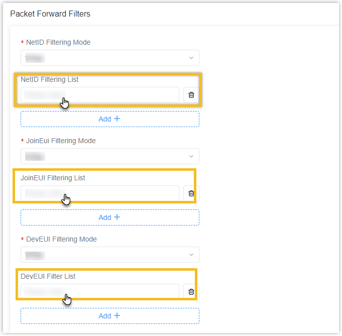
- Set the specific filtering value or range list. Every condition supports to
add 5 lists at most.
Step 8. Configure the Cellular
- Specify the cellular information
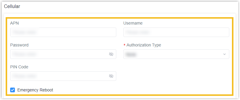
Setting Description APN Specify the Access Point Name for cellular dial-up connection provided by local ISP. Please contact cellular operator or search for the Internet to get it.
Username Specify the username for cellular dial-up connection provided by local ISP.
Password Specify the password for cellular dial-up connection provided by local ISP. Authorization Type Select from None, PAP and CHAP.
PIN Code Specify a 4-8 characters PIN code to unlock the SIM.
Emergency Reboot Click to enable the device reboot when the cellular connection is not available. - Specify the Ping Detection.
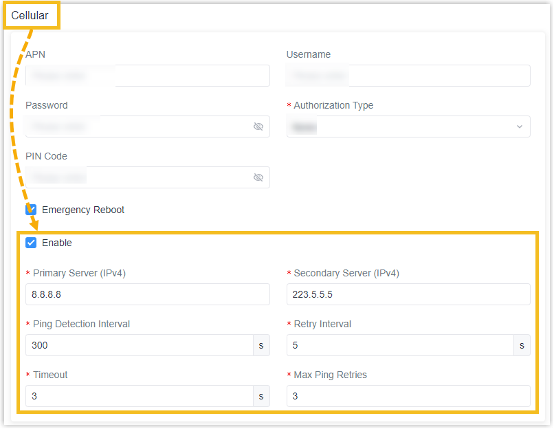
Setting Description Enable
Click to enable and then the device will send ICMP packets to corresponding servers to detect the connection periodically.
Note: It is suggested to disable this option if the device is connected to the private network (Non-internet).Primary Server (IPv4)
The device will send ICMP packet to this server address or hostname to determine whether the Internet connection is still available or not.
Secondary Server (IPv4)
The device will try to ping the secondary server name if primary server is not available.
Ping Detection Interval
Time interval between two Pings. (Unit: s)
Retry Interval
When ping failed, the device will ping again at every retry interval. (Unit: s)
Timeout
The maximum time which the device will wait for a response to a ping request. If it does not receive a response for the timeout, the ping request will be considered to have failed.
Max Ping Retries The number of times the device will retry sending a ping request until determining that the connection has failed.
Step 9. Configure the WLAN
- Click to enable Wi-Fi feature.

- Specify the information of the Wi-Fi feature.
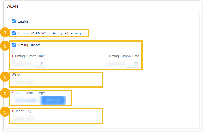
- You can click to enable the Turn off WLAN When Battery is Discharging as needed. The device will turn off the Wi-Fi when the battery is discharging to save power.
- You can click to enable the Timing Turnoff as needed. The device will turn off and turn on the Wi-Fi at preset time points of a day.
- Specify the SSID as needed. The unique name for this device Wi-Fi access point. The default SSID is Gateway_xxxxxx. (xxxxxx is the last 6 digits of MAC address.)
- Specify the Authentication Type. No Encryption and WPA-PSK are optional.
- Specify the Secret Key. And you can customize the Wi-Fi password when security mode is WPA-PSK.
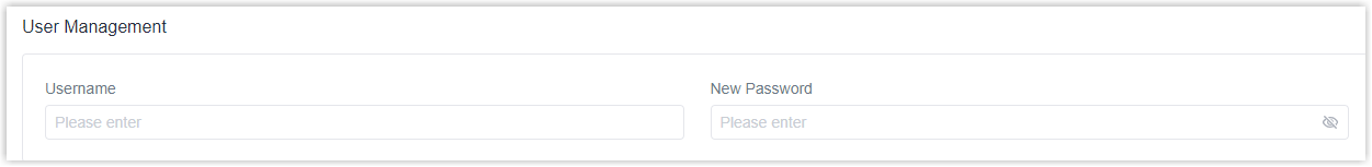
Step 10. Configure the User Management
In the User Management section, you can specify the user name and a new password of the device.
Step 11. Configure the Time
In the Time section, specify the time settings of the device.
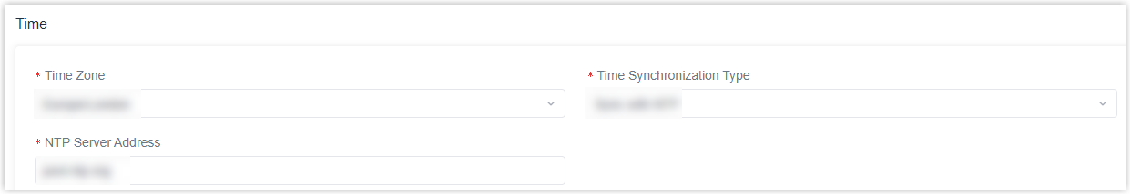
- Specify the Time Zone you are in.
- Show the Time Synchronization Type, it’s fixed as Sync with NTP Server.
- Specify the NTP Server's IP address or domain name.
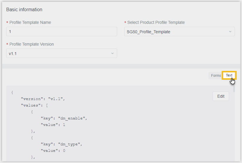
Optional: Step 12. Configure the advanced settings
- Scroll up to the top of the page, click TEXT on the
right to view the settings in JSON.
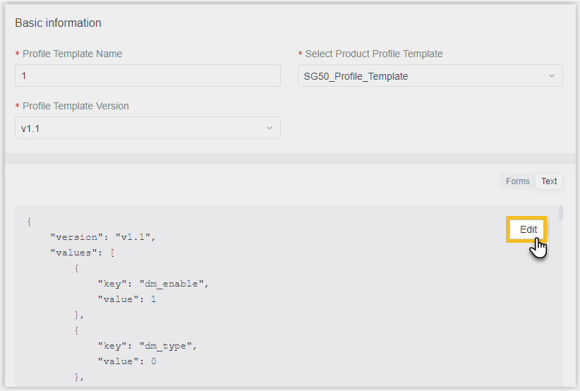
- Click Edit to enter edit mode.
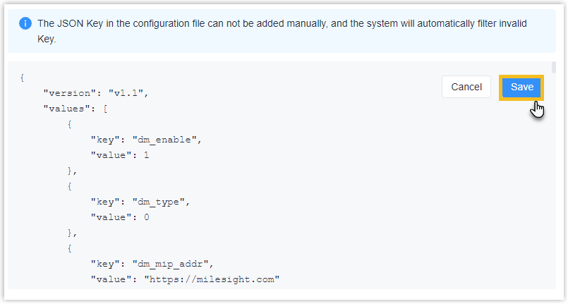
- Search and edit the following keys' value as needed.
Key Type Description station_lns_uri LNS URI Enter the URI address of the remote LoRaWAN server's Basic Station. pkt_keepalive_intv Keep Alive Interval/s Show the time interval for the gateway sends heartbeat packets to the network server. pkt_stat_intv Statistical Time Interval Show the time interval at the gateway updates statistical data. pkt_push_ms Push Timeout Time Show the timeout period for the gateway to receive a response from the server after forwarding the data packet. expert_enable Lora Custom Configuration Enable Decide whether to enable LoRa custom configuration feature. Valid value:
0: Disable. (Default value)1: Enable.
expert_content LoRa Custom Configuration To set custom parameters related to LoRa. - Click Save.
Step 13. Save the custom Profile template
- On the left-bottom of the page, click Save.
- Apply the custom Profile template according to the operation method.
- Web page: Select the Profile template when adding devices.
- API: Do as follow:
- In the Operation column, click
 to download the Profile in
JSON.
to download the Profile in
JSON.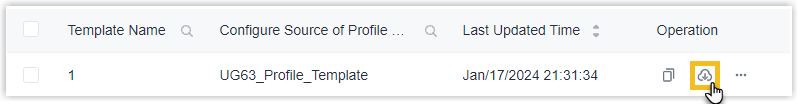
- Include the entire JSON in the API request of Add a Device.
- In the Operation column, click