VS135-P Custom Profile Template
This topic describes how to create a custom Profile template for VS135-P.
Background information
A Profile template contains both Basic Settings and Advanced Settings. Basic settings can edited with the visual interface provided by Milesight Development Platform, while the advanced settings can ONLY be edited in JSON format.
Follow the workflow below to create and apply a custom Profile template:
- Create a custom Profile template on Milesight Development Platform.
- Configure the basic settings with the visual interface.
- Configure the advanced settings in the JSON format.
- Save and apply the custom Profile template accordingly.
Step 1. Create a custom Profile template
- Log in to Milesight Development Platform.
- On the top bar, click Resource,
then select the My Config
tab.
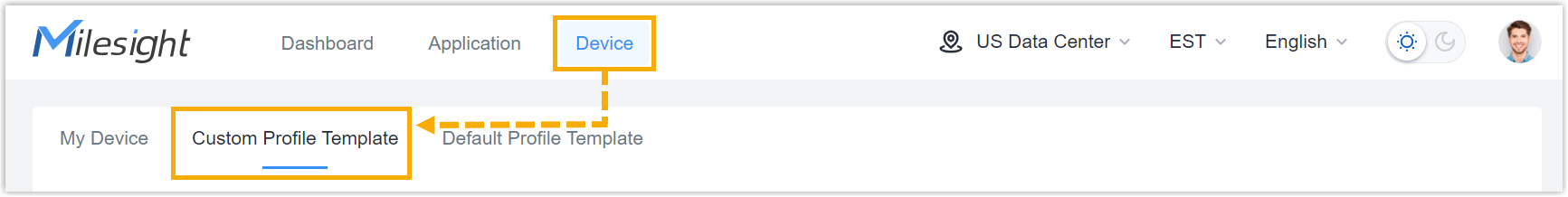
- Click Add.
- In the Basic Configuration section, configure the
basic information:
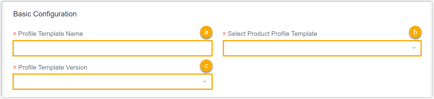
- In the Config Template Name field, specify a name to help you identify this template.
- In the Select Product Config Template field, search and select VS135-P(-HIGH)_Profile_Template.
- In the Config Template Version drop-down list, select the version of the Profile template.
Step 2. Configure the connecting platform
- Select the Generic Configuration tab.
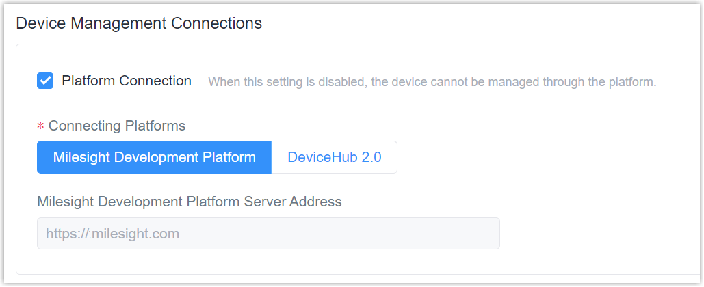
- In the Device Management Connections section, decide
whether to connect the device to Milesight platform for remote management
and configuration.
- Connect the device to Milesight Development Platform
- Retain the default settings.
- Connect the device to Milesight DeviceHub
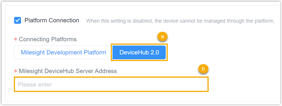
- In the Connecting Platforms field, select DeviceHub 2.0.
- In the Milesight DeviceHub Server Address field, enter the server address of the Milesight DeviceHub.
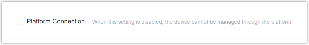
- Do NOT connect to Milesight platform
- Uncheck the Platform Connection.
Step 3. Configure the Dashboard settings
- Select the Basic Configuration tab, then go to the
Dashboard section.
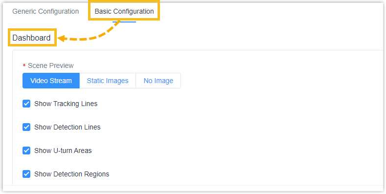
- In the Scene Preview section, specify the scene preview
mode of the device.
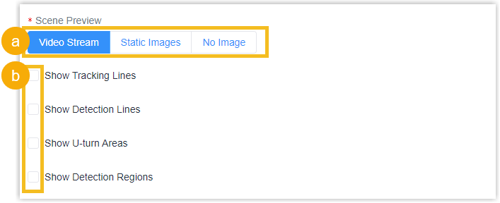
- Select the preview mode.
- Specify the relevant areas show of the detected function by clicking the checkbox.
Step 4. Configure the function Rule
- Go to the Rule section, specify the Working
Mode of the device.
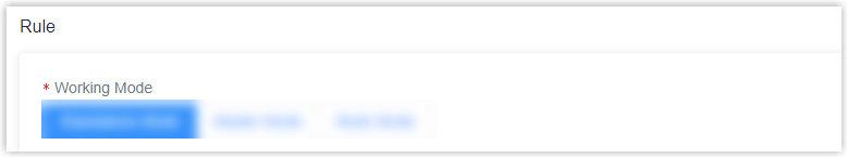
The device supports 3 working modes:
Setting Description Standalone Mode Works as a standalone device to count people. Master Mode Works as a master device to receive live view and tracks fromother node devices. One master device can connect 7 node devices at most. Node Mode Works as a node device to forward live view and tracks to the master device. - In the Rule section, specify corresponding rules
based on different working modes.
Setting Description Standalone Mode Tracking To specify tracking mode of counting. Head Tracking and Feet Tracking are optional. Note:- Feet Tracking is the default option when the working mode is standalone mode.
- It is recommended to use heads tracking mode when the installation height is low in standalone working mode.
Standalone Mode or
Master ModeInstallation Height To set the device installation height. Maximum Target Height To set the maximum target height, then the device will ignore the objects higher than this setting value.
Minimum Target Height To set the minimum target height, then the device will ignore the object shorter than this setting value.
Enhanced Detection Mode Turn on when any one of the following situations occurs, it will ensure normal counting and detecting:
- The depth image is abnormal;
- There is obstacle in the live view;
- Installation conditions are not met.
Children/Adults Differentiation Child Filter Height: To set the max child height when children distinction feature is enabled.
And then the device will detect the people shorter than child filter height as children.
Staff Detection Click to detect the people who wear reflective stripes as staff tags on the visible parts (neck, shoulders, etc.) as staffs.
Note: Reflective stripe requirements: width > 2cm, about 500 cd/lux.m2Group Counting Click to enable the group counting function that based on the distance, moving direction and speed difference to gain deeper insights into customer’ behaviors.
Note: This function is only applicable for line cross people counting.Shopping Cart Level Detection Fully Loaded Cart Height: To set fully loaded cart height when shopping cart fill level detection feature is enabled.
Empty Cart Height: To set empty cart height when shopping cart fill level detection feature is enabled.
And then the device will count the cart as full when the objects inside cart higher than fully loaded cart height, and will count the cart as empty when the objects inside cart shorter than empty cart height.
Heat Map Click to enable Heat Map function, which can analyze person movement with the intuitive and accurate statistical analysis results in time or space pattern as needed.
U-turn Filtering Click to enable U-turn Filtering, which will count the In and Out values only when people passed the U-turn area for every line.
Region Monitoring Click to enable the region monitoring. Up to 4 regions are supported with maximum 10 segments each.
Reset Cumulative Count on Schedule Click to enable periodically reset cumulative count on schedule.
Cumulative Count includes:
- Total In/Out counting of each detection line.
- Max./Avg. Dwell Time of each detection region.
Line Crossing People Counting Triggered by External Input Click to enable the counting will be initiated only when trigger status is the same as the current status.
- Low Status: Two contacts disconnected
- High Status: Two contacts closure
Trigger Digital Output When trigger event is enabled, the digital output will send a preset width of high level.
Synchronized Pulse Interval: the interval between multiple pulses when several people pass through or multiple events trigger at the same time.
Step 5. Configure the Network settings
- Go to the Network section,
specify the IPv4 assignment method.
Setting Description Manual To manually assign the IPv4 address, do as follow: 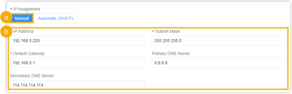
- Select Manual.
- Configure the IPv4 address as needed or retain the default value.
Automatic (DHCP) To automatically assign the IPv4 address, select Automatic (DHCP). 
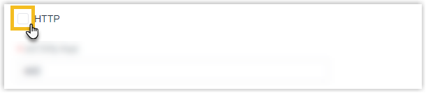
- In the HTTP section, specify whether to enable
the HTTP protocol by clicking the checkbox .
Setting Description HTTP Port To enable the HTTP protocol, do as follow: 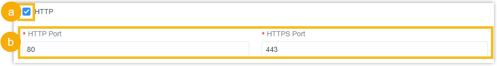
- Click the HTTP checkbox to enable HTTP protocol.
- Configure the HTTP Port and HTTPS Port as needed or retain the default value.
HTTPS Port To disable the HTTP protocol, do not click the HTTP checkbox. 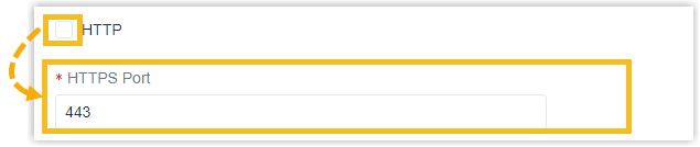
- In the Enable WLAN section,
specify whether to enable WLAN by checking the checkbox and configure the
WLAN AP settings for local web access and configuration.

Setting Description Wi-Fi SSID The unique name for this device Wi-Fi access point. Protocol Select the protocol for Wi-Fi connection.
Bandwidth Select the bandwidth for Wi-Fi connection. Channel Select the channel for Wi-Fi connection. Security Mode Select the security mode for Wi-Fi connection.
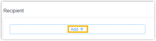
Step 6. Configure the Recipient settings
- Go to the Recipient Settings section, then click
Add+ to add the recipients of device.
- In the Recipient section, specify the data receivers.
The device will proactively push data to the receivers according to the
configured reporting scheme.Note:
- Up to 8 receivers can be added.
- When working mode is the Node mode, the device will not support Recipients settings.
Setting Description Name Customize the recipient name.
Report Protocol HTTP(S) To set the reporting protocol as HTTP(S), do as follow: - Select HTTP(S) report protocol.
- Configure the HTTP(S) information as needed.
MQTT To set the reporting protocol as MQTT, do as follow: - Select MQTT report protocol.
- Configure the MQTT information as needed or retain the default value.
- In the TLS Type field,
click to enable and specify the certificate type
for TLS.
- To use the CA-signed TLS certificate, select CA Signed Server.
- To use Self-signed TLS certificate, select Self Signed and upload the required certificate files.
Trigger Report Report immediately when there is a change of the line crossing people counting number or region people counting number.
Periodic Report Select the periodic report of "On the Dot" or "From Now On". On the Dot: The device will report at the top of each hour. For example, When the interval is set to 1 hour, it will report at 0:00, 1:00, 2:00 and so on; when the interval is set to 10 minutes, it will report at 0:10, 0:20, 0:30, and so on.
From Now On: Begin reporting from this moment onwards and regularly report based on the interval cycle.
Data Retransmission Click to enable resend stored data packets from the disconnected period when the device's network connection is restored.Note: A maximum of for each recipient can be resent.Device Info Customizable selection of content to be reported, avoiding data redundancy.
Line Trigger Data Region Trigger Data Line Periodic Data Line Total Data Region Period Data Line/Region Name Line/Region UUID
Step 7. Configure the System Settings
- Go to the System Settings section.
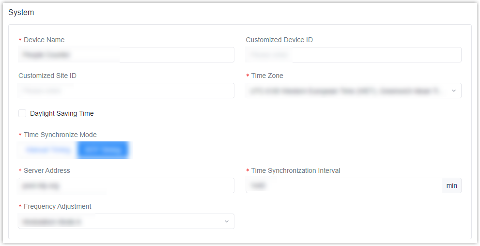
- In the Device Name field, specify a name to help you identify this device.
- You can specify a Device ID and a Site ID for this device as needed.
- In the Time Zone drop-down list, select the desired time zone for this device.
- In the Daylight Saving Time field, decide whether to
enable Daylight Saving Time (DST) for this device.
- Off: Disable DST for this device.
- Automatic: Enable DST for this device.
- In the Time Synchronize Mode section, specify the
time synchronization mode.
- Manual: Manually synchronize the device's time.
- NTP Timing: Synchronize the device's time
across a network using the Network Time Protocol.
You can specify the Server Address and Time Synchronization Interval as needed.
- In the Frequency Adjustment drop-down list, select the modulation mode.
- In the ToF Lighting Mode drop-down list, select the ToF lighting mode.
- Check the checkbox of Tilt Correction if the device is mounted at a tilt.
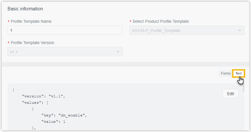
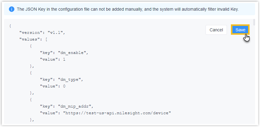
Optional: Step 8. Configure the advanced settings
- Scroll up to the top of the page, click TEXT on the
right to view the settings in JSON.
- Click Edit to enter edit mode.
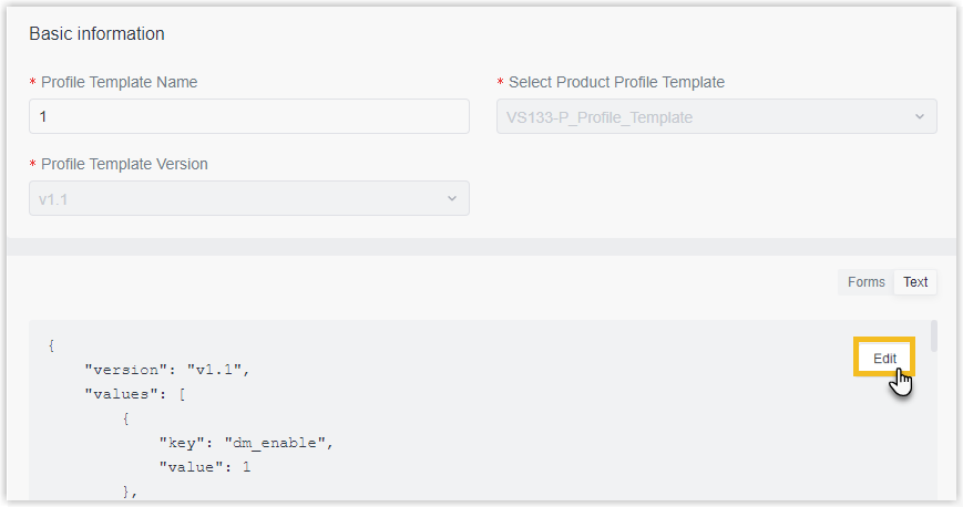
- Search and edit the following keys' value as needed.
Key Type Description image_type Integer Specify the image type of the device. Valid value
0: Grayscale image.1: Pseudocolor image.
- Click Save.
Step 9. Save the custom Profile template
- On the left-bottom of the page, click Save.
- Apply the custom Profile template according to the operation method.
- Web page: Select the Profile template when adding devices.
- API: Do as follow:
- In the Operation column, click
 to download the Profile in
JSON.
to download the Profile in
JSON.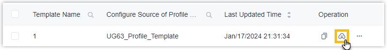
- Include the entire JSON in the API request of Add a Device.
- In the Operation column, click